Analogue input (AI1) or (AI2) – purple terminal
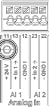
Analogue signal sources connected to terminals 12 and 13 for use with AI1 and connected to terminals 22 and 23 for use with AI2
Note correct polarity for signals 0 – 10 V, 2 – 10 V, 0 – 20 mA and 4 – 20 mA.
Use the pump to supply 24 V DC to an active sensor. For this purpose, pick off the voltage at +24 V (11) and GND I (12) terminals.
The analogue inputs can be used for the following functions:
- External setpoint specification
- Sensor connection:
- Temperature sensor
- Differential pressure sensor
- PID sensor
Analogue input for following signals:
- 0 – 10 V
- 2 – 10 V
- 0 – 20 mA
- 4 – 20 mA
- PT1000
Technical data:
- Analogue input load (0) 4 – 20 mA: ≤ 300 Ω
- Load resistance at 0 – 10 V, 2 – 10 V: ≥ 10 kΩ
- Dielectric strength: 30 V DC / 24 V AC
- Terminal for supplying active sensors with 24 V DC – maximum power load: 50 mA
NOTICE
See section 10.5 “Application and function of analogue inputs AI1 and AI2”
CAUTION
Overload or short-circuit
In case of overload or short-circuit of the 24 V connection, all input functions will fail (analogue inputs and digital inputs).
The input functions will be available again when the overload or short-circuit situation is resolved.
CAUTION
Overvoltages destroy the electronics
Analogue and digital inputs are protected for overvoltages up to 30 V DC / 24 V AC. Higher overvoltages destroy the electronics.