Digital input (DI1) or (DI2) – grey terminal block
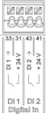
The pump can be controlled with the following functions via external potential-free contacts (relay or switch) at the DI 1 or DI 2 digital inputs:
Function control input DI 1 or DI 2 | |
|---|---|
External OFF | Contact open: Pump switched off. Contact closed: Pump is switched on. |
• External MAX | Contact open: Pump is running in the mode set on the pump. Contact closed: Pump is running with maximum speed. |
• External MIN | Contact open: Pump is running in the mode set on the pump. Contact closed: Pump is running with minimum speed. |
• External MANUAL | Contact open: Pump is running in the mode set Contact closed: Pump is set to MANUAL. |
• External key lock | Contact open: Key lock is deactivated. Contact closed: Key lock is activated. |
Heating/cooling switchover | Contact open: “Heating” active. Contact closed: “Cooling” active. |
Technical data:
- Maximum voltage: < 30 V DC / 24 V AC
- Maximum loop current: < 5 mA
- Operating voltage: 24 V DC
Operating loop current: 2 mA (per input)
NOTICE
See section 8.6 “Adjustment - Manual operation” and section 10.4 “Application and function of the digital control inputs DI 1 and DI 2” for a description of the functions and their priorities.
CAUTION
Overload or short-circuit
In case of overload or short-circuit of the 24 V connection with GND, all input functions will fail (analogue inputs and digital inputs).
The input functions will be available again when the overload or short-circuit situation is resolved.
CAUTION
Overvoltages destroy the electronics
Analogue and digital inputs are protected for overvoltages up to 30 V DC / 24 V AC. Higher overvoltages destroy the electronics.
CAUTION
Digital inputs must not be used for safety-oriented shutdowns!