Menu 5: Basic settings
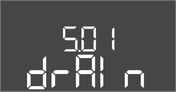
Menu no. | 5.01 |
Software version: All | |
Description | Operating mode |
Value range | fill, drain |
Factory setting | drain |
Explanation |
|
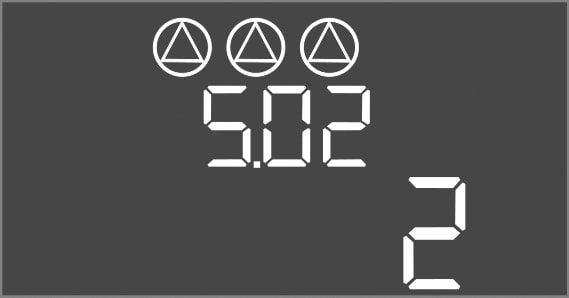
Menu no. | 5.02 |
Software version: All | |
Description | Number of connected pumps |
Value range | 1 … 3 |
Factory setting | 2 |
Menu no. | 5.03 |
Software version: All | |
Description | Standby pump |
Value range | on, off |
Factory setting | off |
Explanation | One pump can be used as a standby pump. This pump is not activated during normal operation. The standby pump is only activated in the event of pump failure due to a fault. The standby pump is subject to standstill monitoring. The standby pump is therefore activated during pump cycling and pump kick.
|

Menu no. | 5.07 |
Software version: Up to 2.01.x | |
Description | Signal transmitter for level measurement |
Value range | Float, Level, Bell, Opt01 |
Factory setting | Level |
Explanation | Definition of the signal transmitters for level measurement:
|
Software version: from 2.02.xand hardware version: 2 | |
Description | Signal transmitter for level measurement |
Value range | Float, Level, Bell, Opt01 |
Factory setting | Level |
Explanation | Definition of the signal transmitters for level measurement:
|

Menu no. | 5.09 |
Software version: All | |
Description | Sensor measurement range |
Value range | 0.25 ... 12.5 m |
Factory setting | 1.0 m |
Explanation | Maximum measured values of the sensor |

Menu no. | 5.39 |
Software version: All | |
Description | Alarm signal with active “Extern OFF” input |
Value range | off, on |
Factory setting | off |
Explanation | The pumps can be switched off using a separate signal transmitter via the “Extern OFF” input. This function overrides all other switching points and all pumps are switched off.
|

Menu no. | 5.40 |
Software version: All | |
Description | Switch “pump kick” function On/Off |
Value range | off, on |
Factory setting | off |
Explanation | To prevent longer standstill times for the connected pumps, a periodical test run can be performed (pump kick function):
If the pump kick function is activated, the following menu items can be set:
|

Menu no. | 5.41 |
Software version: All | |
Description | Allows “pump kick” when status is Extern OFF |
Value range | off, on |
Factory setting | on |
Explanation | Select whether a pump kick may take place or not if the Extern OFF input is active:
|

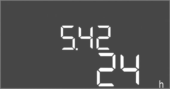
Menu no. | 5.42 |
Software version: All | |
Description | “Pump kick interval” |
Value range | 1 … 336 h |
Factory setting | 24 h |
Explanation | Time after which a pump kick takes place. |
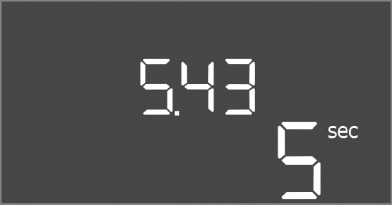
Menu no. | 5.43 |
Software version: All | |
Description | “Pump kick duration” |
Value range | 0 … 60 s |
Factory setting | 5 s |
Explanation | How long a pump kick runs for a pump. |
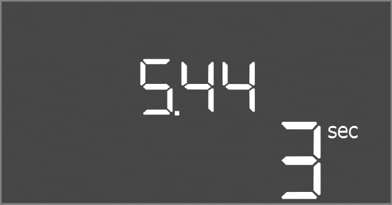
Menu no. | 5.44 |
Software version: All | |
Description | Activation delay after power failure |
Value range | 0 … 180 s |
Factory setting | 3 s |
Explanation | Time until the switchgear automatically restarts after a power outage. |
Menu no. | 5.50 |
Software version: All | |
Description | Dry-running level (drain)/ min. water level (fill) |
Value range | 0 ... 12.5 m |
Factory setting | 0.15 m |
Explanation | Enter fill level. If the level is monitored with a separate float switch, deactivate the level sensor: Enter the value “0.00 m”. |

Menu no. | 5.51 |
Software version: All | |
Description | High water level |
Value range | 0 ... 12.5 m |
Factory setting | 0.46 m |
Explanation | Enter fill level. |

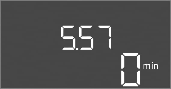
Menu no. | 5.57 |
Software version: All | |
Description | Max. running time per pump |
Value range | 0 … 60 min |
Factory setting | 0 min |
Explanation | Maximum permissible running time of a pump. Once the time has been exceeded, the system switches to the next pump. After three change cycles, the collective fault signal (SSM) is activated. |
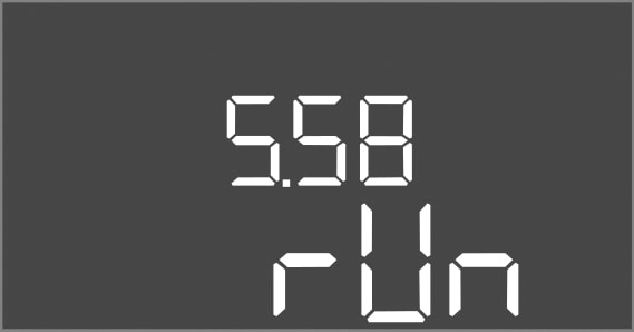
Menu no. | 5.58 |
Software version: All | |
Description | Collective run signal (SBM) function |
Value range | on, run |
Factory setting | run |
Explanation | A run signal for the switchgear or attached pump can sent via a separate output:
|
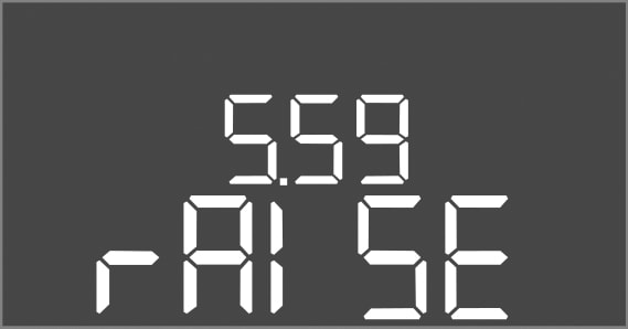
Menu no. | 5.59 |
Software version: All | |
Description | Collective fault signal (SSM) function |
Value range | fall, raise |
Factory setting | raise |
Explanation | In case of an error, a general fault message can be sent via a separate output:
|
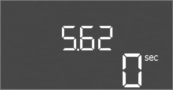
Menu no. | 5.62 |
Software version: All | |
Description | Dry-running protection delay |
Value range | 0 … 180 s |
Factory setting | 0 s |
Explanation | Time until the pump are deactivated after reaching the dry run level. |
Menu no. | 5.64 |
Software version: All | |
Description | Ex-mode On/Off (only available in the “drain” operating mode!) |
Value range | on, off |
Factory setting | off |
Explanation | The following functions are adjusted when the Ex-mode is activated (on):
Observe the additional requirements in the chapter on explosive atmospheres in the appendix! |

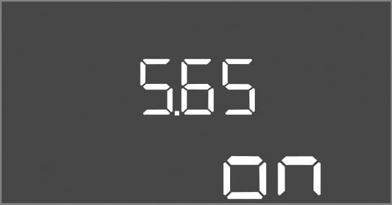
Menu no. | 5.65 |
Software version: All | |
Description | Automatic resetting of error “Dry run” |
Value range | on, off |
Factory setting | on |
Explanation | If the fill level is over the dry run level again, the error message “dry run” is automatically reset.
|
Menu no. | 5.66 |
Software version: All | |
Description | Integrated buzzer On/Off |
Value range | off, error |
Factory setting | off |
Explanation | Switching the buzzer on or off:
|

Menu no. | 5.67 |
Software version: All | |
Description | Output (24 V=, max. 4 VA) On/Off for an external signalling unit |
Value range | off, error |
Factory setting | off |
Explanation | Separate output to switch an external alarm signal on or off:
|

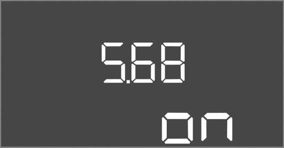
Menu no. | 5.68 |
Software version: All | |
Description | Mains connection rotating field monitoring On/Off |
Value range | on, off |
Factory setting | on |
Explanation | Integrated rotating field monitoring for the mains connection. If no clockwise rotating field is present, an error message occurs.
|
Menu no. | 5.69 |
Software version: Up to 2.01.x | |
Description | Motor current monitoring On/Off |
Value range | on, off |
Factory setting | on |
Explanation | The integrated motor current monitoring outputs an error if the set rated current is exceeded.
|
Software version: From 2.02.x | |
Description | Motor current monitoring On/Off |
Value range | on, off |
Factory setting | on |
Explanation | The integrated motor current monitoring keeps tab on the minimum and maximum rated current of the pump:
This function can be set as follows:
|

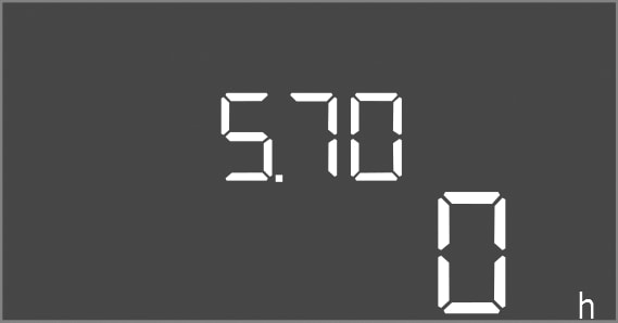
Menu no. | 5.70 |
Software version: All | |
Description | Max. switching frequency per hour, per pump |
Value range | 0 … 60 |
Factory setting | 0 |
Explanation | If the max. number of starts has been exceeded, the collective fault signal (SSM) is activated. To deactivate the function, set the value “0”. |