During operation
Make sure the following points are observed during operation:
- Keep the switchgear closed and secure it against unauthorised opening.
- Switchgear attached in an overflow-proof manner (protection class IP54).
- Not exposed to direct sunlight.
- Ambient temperature: 0 … 40 °C.
The following items of information are shown on the main screen:
- Pump status:
- Number of registered pumps
- Pump activated/deactivated
- Pump On/Off
- Operation with standby pump
- Control mode
- Actual pressure value or float switch status
- Active fieldbus operation
Furthermore, the following information is available via Menu 4:
- Press the control knob for 3 s.
- Menu 1.00 appears.
- Turn the control knob until Menu 4 appears.
- Press the control knob.
- Menu 4.xx appears.
Menu no. | 4.00 |
Name | Information |
Description | Current operating data for pumps and switchgear |

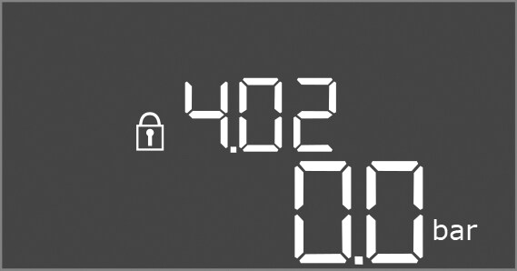
Menu no. | 4.02 |
Name | Actual pressure value in bar |
Value range | 0.0 – 25.0 bar |
Factory setting | 0.0 bar |
Description | Value measured by the pressure sensor on the output side. |
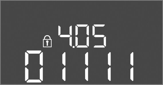
Menu no. | 4.05 |
Name | Status of float switches |
Value range | 0, 1 |
Description | Float switch status:
If necessary, the status of all float switches is indicated by alternating lines on the display. |
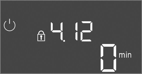
Menu no. | 4.12 |
Name | Switchgear running time |
Description | Total runtime during which the switchgear was supplied with voltage. |
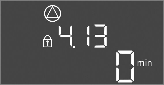
Menu no. | 4.13 |
Name | Running time pump 1 |
Description | Operating hours of pump 1 with rotating motor. |
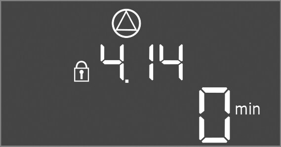
Menu no. | 4.14 |
Name | Running time pump 2 |
Description | Operating hours of pump 2 with rotating motor. |
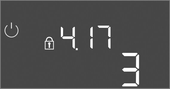
Menu no. | 4.17 |
Name | Switching cycles of switchgear |
Value range | 0 – 65535 |
Description | Number of starts and stops for the switchgear |
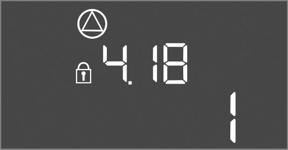
Menu no. | 4.18 |
Name | Switching cycles of pump 1 |
Value range | 0 – 65535 |
Description | Number of starts and stops for pump 1 |
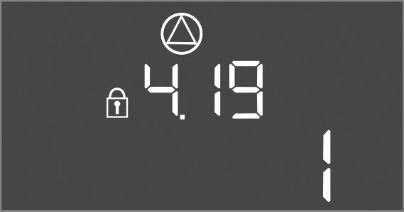
Menu no. | 4.19 |
Name | Switching cycles of pump 2 |
Value range | 0 – 65535 |
Description | Number of starts and stops for pump 2 |
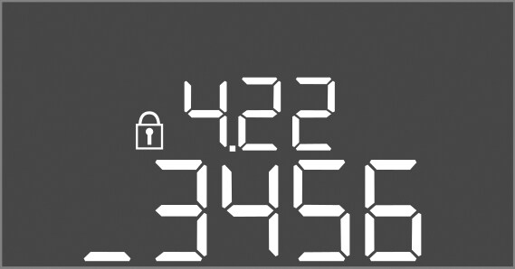
Menu no. | 4.22 |
Name | Serial number switchgear |
Description | The serial number can be changed as long as the number of switching cycles of the switchgear is less than or equal to 5. After that, it can no longer be changed. |
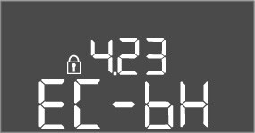
Menu no. | 4.23 |
Name | Switchgear type |
Value range | EC-bH |
Factory setting | EC-bH |
Description | Type of switchgear, for Control EC-WP always EC-bH (borehole) |
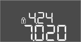
Menu no. | 4.24 |
Name | Software version |
Description | Version for the software used in the switchgear |
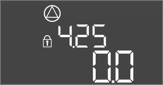
Menu no. | 4.25 |
Name | Set value for the motor current monitoring: Pump 1 |
Value range | 0.0 – 12.0 |
Factory setting | 0.0 |
Description | Value for the maximum rated current in A for pump 1, which was set on the potentiometer on the printed circuit board. |
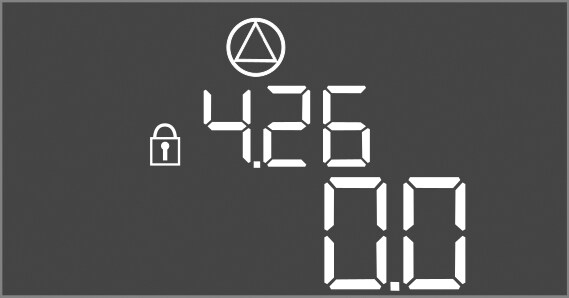
Menu no. | 4.26 |
Name | Set value for the motor current monitoring: Pump 2 |
Value range | 0.0 – 12.0 |
Factory setting | 0.0 |
Description | Value for the maximum rated current in A for pump 2, which was set on the potentiometer on the printed circuit board. |
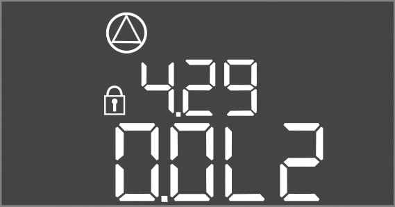
Menu no. | 4.29 |
Name | Actual current in A for pump 1 |
Description | Displays the current measured in A for pump 1:
|
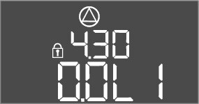
Menu no. | 4.30 |
Name | Actual current in A for pump 2 |
Description | Displays the current measured in A for pump 2:
|