Menu 5: Basic settings
Menu no. | 5.00 |
Name | Installation |
Description | Settings made during the installation of the switchgear. |

Menu no. | 5.01 |
Name | Control mode |
Value range | fill, drain, p-c |
Factory setting | drain |
Description | The active control mode of the switchgear. It is selected depending on the intended application.
|

Menu no. | 5.02 |
Name | Number of pumps |
Value range | 1 … 2 |
Factory setting | 1 |
Description | Number of pumps in the system |

Menu no. | 5.03 |
Name | Standby pump |
Value range | on, off |
Factory setting | off |
Description | Determines whether or not a pump should be kept in stock as a replacement for a failed pump. One pump can be used as a standby pump. This pump is not activated during normal operation. The standby pump is only activated in the event of pump failure due to a fault. The standby pump is subject to standstill monitoring. The standby pump is therefore activated during pump cycling and pump kick.
|

Menu no. | 5.06 |
Name | Signal acquisition pressure |
Value range | digi, senso |
Factory setting | senso |
Description | Determines whether the pressure is measured by a pressure switch or an analogue pressure sensor. digi = pressure switch senso = pressure sensor |

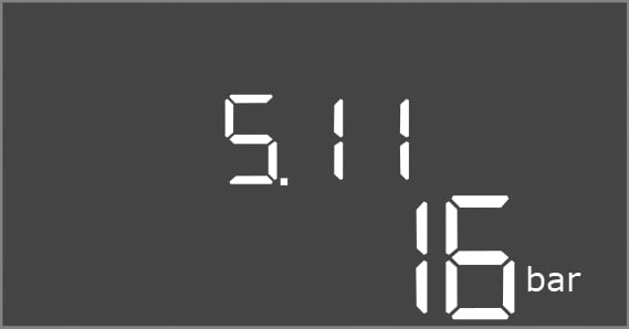
Menu no. | 5.11 |
Name | Pressure sensor measurement range |
Value range | 4 – 25 bar |
Factory setting | 16 bar |
Description | Defines the end value for the pressure range of the sensor. |
Menu no. | 5.39 |
Name | Alarm signal with active “Extern OFF” input |
Value range | off, on |
Factory setting | off |
Description | If “Extern OFF” is used as input for a float switch, a “Priority Off” alarm can be activated. |

Menu no. | 5.40 |
Name | Pump kick |
Value range | off, on |
Factory setting | on |
Description | Switch the “Pump kick” function on or off:
|

Menu no. | 5.41 |
Name | “Pump kick” for Extern OFF |
Value range | off, on |
Factory setting | on |
Description | Select whether a pump kick may take place or not if the Extern OFF input is active:
|

Menu no. | 5.42 |
Name | “Pump kick interval” |
Value range | 1 … 336 h |
Factory setting | 24 h |
Description | The time interval between two test runs or after all pumps have stopped. |

Menu no. | 5.43 |
Name | “Pump kick” duration |
Value range | 0 … 60 s |
Factory setting | 5 s |
Description | The switch-on time of the pump during the test run |

Menu no. | 5.44 |
Name | Delay system |
Value range | 0 – 180 s |
Factory setting | 3 s |
Description | Waiting time after activation of the switchgear until a pump can be started. This can be utilised when using several switchgears in order to reduce power peaks by starting them simultaneously. |

Menu no. | 5.45 |
Name | Number of pumps with sensor error |
Value range | 0 – 4 |
Factory setting | 0 |
Description | Defines the number of pumps to be started if a sensor error has occurred. |

Menu no. | 5.57 |
Name | Maximum running time for single-pump operation |
Value range | 0 … 60 min |
Factory setting | 0 min |
Description | If only one pump is activated and exceeds the set maximum running time, an alarm is generated. The setting “0 min” switches the running time monitoring off. |

Menu no. | 5.58 |
Name | Collective run signal (SBM) behaviour |
Value range | on, run |
Factory setting | run |
Description | The mode for the collective run signal:
|

Menu no. | 5.59 |
Name | Collective fault signal (SSM) behaviour |
Value range | fall, raise |
Factory setting | raise |
Description | The switching behaviour of the collective fault signal:
|

Menu no. | 5.60 |
Name | Pump cycling |
Value range | on, off |
Factory setting | on |
Description | Activate or deactivate automatic pump cycling after 6 hours of operation.
|

Menu no. | 5.62 |
Name | Delay dry-running protection |
Value range | 0 – 180 s |
Factory setting | 0 s |
Description | The delay for detecting dry run to avoid false alarms caused by short impulses. |

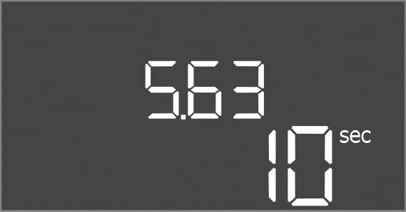
Menu no. | 5.63 |
Name | Delay restart after dry run |
Value range | 0 – 1800 s |
Factory setting | 10 s |
Description | Time until the pumps start again after the end of the dry running signal. |
Menu no. | 5.66 |
Name | Acoustic alarm |
Value range | off, error |
Factory setting | off |
Description | Enables the activation of an acoustic signal when an alarm occurs.
|

Menu no. | 5.67 |
Name | Output for an external signalling unit On/Off |
Value range | off, error |
Factory setting | off |
Description | Enables the activation of an optical signal when an alarm occurs.
|

Menu no. | 5.68 |
Name | Rotating field detection |
Value range | on, off |
Factory setting | on |
Description | Activation or deactivation of the phase rotating field detection when single-phase pumps are used.
|

Menu no. | 5.69 |
Name | Minimum current detection pumps |
Value range | on, off |
Factory setting | on |
Description | Activate or deactivate undercurrent detection for the pumps: If the motor current is below the set minimum, the minimum current detection reports an error.
|

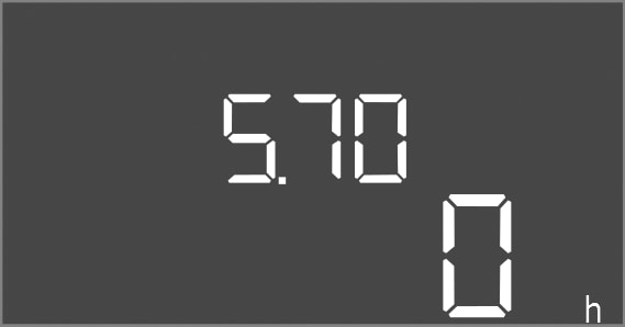
Menu no. | 5.70 |
Name | Max. switching frequency per hour, per pump |
Value range | 0 … 60 |
Factory setting | 0 |
Description | If the max. number of starts has been exceeded, an alarm is generated. To deactivate the function, set the value “0”. |
Menu no. | 5.71 |
Name | Number of wells |
Value range | 1 … 2 |
Factory setting | 1 |
Description | Number of wells for systems with 2 pumps. This has an effect on dry-running detection and pump selection. For 1 pump, the number is always 1. |

Menu no. | 5.72 |
Name | Number of float switches for pump levels |
Value range | 1 – 4 |
Factory setting | 1 |
Description | The total number of float switches for controlling pump start and pump stop. Setting options:
|
