Step 1 – Wilo Net, termination, addressing
To set up Multi-Flow Adaptation, the electrical wiring must first be established via the “Wilo Net” interface between the feeder pump and the secondary pump(s). Wilo Net is a Wilo system bus used for establishing communication between Wilo products. In order to establish the Wilo Net connection, the three H, L, GND terminals must be wired with a communication cable from pump to pump.
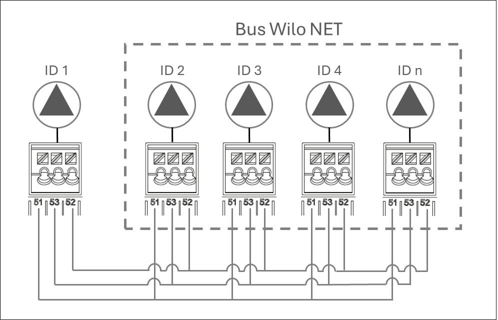
Use shielded cables for cable lengths ≥ 2 m. Incoming and outgoing cables are clamped in a terminal. Incoming and outgoing cables must be fitted with double-wire end sleeves. To ensure interference immunity in industrial environments (IEC 61000-6-2), use a shielded CAN bus cable and an EMC-compatible cable entry for the Wilo Net cables. Connect the shield to earth at both ends. For optimum transmission, the data cable pair (H and L) must be twisted at Wilo Net and have a characteristic impedance of 120 ohms. Maximum cable length 200 m. Possible cable for Wilo Net communication: CAN-Bus cable 2x2x0.34 mm².
In the Wilo Net, a maximum of 21 participants (from pump software SW 01.04.19.00) can communicate with each other, each individual node counting as a participant here, i.e., a twin-head pump/two-pump system consists of two participants.
Twin-head pump in the Wilo Net network
If twin-head pumps are added to a larger Wilo Net network (e.g. Multi-Flow Adaptation), the local Wilo Net twin-head pumps must be adapted to the large system.
As a factory setting, the two pump heads each have ID 1 and ID 2 and termination activated.
For integration into a larger Wilo Net network, deactivate at least one termination, depending on the position in which the twin-head pump is integrated in the Wilo Net segment.
Changing Wilo Net ID and termination for a generic twin-head pump
With the operation on pump head I of a twin-head pump (with graphic display), only the Wilo Net ID and termination of this pump head can be changed. In order to be able to assign new Wilo Net IDs to both pump heads of a twin-head pump, the twin-head pump system must first be disbanded and the new ID (e.g. “4”) must be set on pump head I. If necessary, the termination must be deactivated beforehand. Then the graphic display must be changed from pump head I to pump head II in order to adjust the Wilo Net ID (e.g. “5”) there as well.
In the  “Settings” menu, select the following in sequence:
- “External interfaces”
- “Wilo Net setting”
- Select “Wilo Net termination”.
- The feeder pump and the last wired secondary pump must be selected as “switched on” when selecting the Wilo Net termination.
- The other secondary pumps must remain “switched off”.
- Select “Wilo Net address” and assign each pump its own address (1 to 21).
Example 1: Multi-Flow Adaptation featuring four pumps:
- Feeder pump (primary circuit pump)
- Wilo Net termination: ON
- Wilo Net address: 1
- Secondary pump 1:
- Wilo Net termination: OFF
- Wilo Net address: 2
- Secondary pump 2:
- Wilo Net termination: OFF
- Wilo Net address: 3
- Secondary pump 3:
- Wilo Net termination: ON
- Wilo Net address: 4
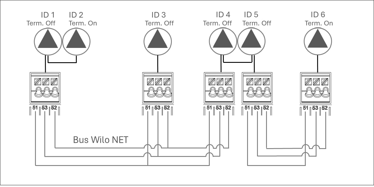
Example 2: The primary circuit pump of a Multi-Flow Adaptation system is a twin-head pump:
- Feeder pump (primary circuit pump)
- Wilo Net termination: ON
- Wilo Net address: 1
- Wilo Net address: 2
- Secondary pump 1:
- Wilo Net termination: OFF
- Wilo Net address: 3
- Secondary pump n=2 to 18
- Wilo Net termination: OFF
- Wilo Net address: 2+n
- Secondary pump n=19:
- Wilo Net termination: ON
- Wilo Net address: 21
In a Multi-Flow Adaptation system with twin-head pumps, a maximum of 5 twin-head pumps can communicate with each other via Wilo Net in the MFA network. In addition to this maximum of 5 twin-head pumps, up to 11 additional single pumps can be included in the network.
After completion of the wiring, termination and addressing, set the pumps according to their application.