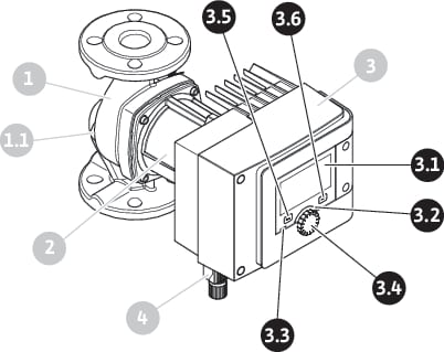
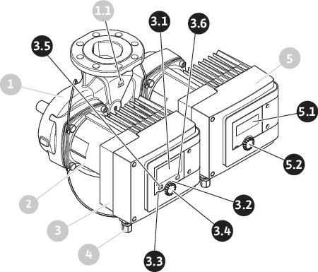
Description of operating elements


Item | Name | Explanation |
|---|---|---|
3.1 | Graphic display | Provides information about settings and pump status. Self-explanatory user interface for setting the pump. The display screen cannot be rotated. |
3.2 | Green LED indicator | LED is lit up: Pump is supplied with voltage and ready for operation. There are no warnings and no faults. |
3.3 | Blue LED indicator | LED is lit up: Pump is influenced externally via an interface, e.g. by: • Bluetooth remote control • Setpoint specification via analogue input AI1 or AI2 • Intervention of building automation via digital input DI1, DI2 or bus communication Flashes with active twin-head pump connection. |
3.4 | Operating knob | Navigate menus and edit content by turning and pressing. |
3.5 | Back button | Menu navigation: • To go back to the previous menu level (briefly press once). • To go back to the previous settings (briefly press once). • Return to the main menu (press and hold 1 x, > 2 seconds) Turns key lock on or off in combination with the Context button. > 5 seconds. |
3.6 | Context button | Opens the context menu with additional options and functions. Turns key lock on or off in combination with the back button. > 5 seconds. |
5.1 | LED display | Indicates error code and Bluetooth PIN. |
5.2 | LED display control knob | Triggers the pump venting function when pressed. Turning is not possible. |