Connecting the communication interfaces
Observe all warnings in the “Electrical Connection” section!
Make sure that all power supplies of the pump and connected communication interfaces, especially that of SSM and SBM, are switched off!
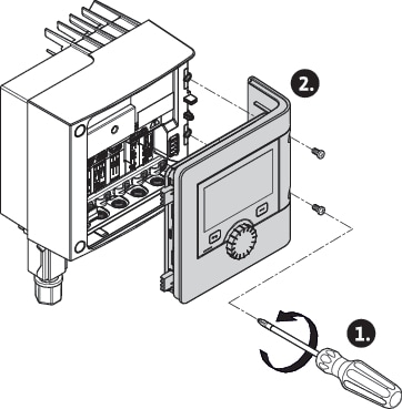
- Loosen the screws of the module cover.
- Remove the module cover and carefully put it to one side.
- Unscrew the required number of screw plugs (M16x1.5) with the tool.
- Undo the required number of shield clamps (see notice).
- Screw in the threaded cable gland M16x1.5 and tighten with a torque of 2.5 Nm.
- Strip communication cables to the required length.
- Push the nut of the threaded cable gland over the cable and insert the cable into the internal seal ring of the threaded cable gland and under the shield clamp.
- Spring clips: Open WAGO “Cage Clamp” by pressing it with a screwdriver and guide the stripped lead into the terminal.
- Fasten communication cables using shield clamps (see notice).
- To ensure strain relief, tighten the nut of the threaded cable gland with a torque of 2.5 Nm.
- Push the module cover forward into the grooves using the guide bars, close cover and fasten with screws.
NOTICE
• Remove the internal sealing ring of the M16x1.5 threaded cable gland when installing cables with a diameter ≥ 5 mm.
Position the cable shielding on only one end of the cable to prevent circulating current in the event of potential difference via the communication cable!
To loosen the leads: Open the WAGO “Cage Clamp” spring clip! Then pull out leads!
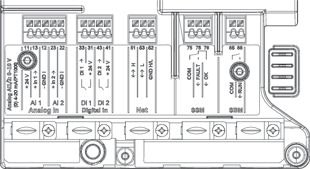
External interfaces
- Analogue IN (purple terminal block)
- Digital IN (grey terminal block)
- Wilo Net (green terminal block)
- SSM (red terminal block)
- SBM (orange terminal block)
All communication interfaces in the terminal room (analogue inputs, digital inputs, Wilo Net, SSM and SBM) comply with the SELV standard.
SSM and SBM can also be operated with/at non-SELV compliant connections/voltage ratings (up to 250 V AC) without this negatively influencing the SELV compliance of the remaining communication connections in the terminal room.
Make sure to install cable ducts correctly and ensure separation in the terminal room to maintain SELV conformity for all other cables.
Cable requirements
Terminals are intended for rigid and flexible conductors with or without ferrules.
Connection | Terminal cross-section in mm2 Min. | Terminal cross-section in mm2 Max. | Cable |
|---|---|---|---|
Mains plug | 3x1.5 | 3x2.5 | |
SSM | 2x0.2 | 2x1.5 (1.0**) | * |
SBM | 2x0.2 | 2x1.5 (1.0**) | * |
Digital input 1 (DI1) | 2x0.2 | 2x1.5 (1.0**) | * |
Digital input 2 (DI2) | 2x0.2 | 2x1.5 (1.0**) | * |
+24 V output | 1x0.2 | 1x1.5 (1.0**) | * |
Analogue input 1 (AI1) | 2x0.2 | 2x1.5 (1.0**) | * |
Analogue input 2 (AI2) | 2x0.2 | 2x1.5 (1.0**) | * |
Wilo Net | 3x0.2 | 3x1.5 (1.0**) | Shielded |
*Cable length ≥ 2 m: Use shielded cables.
**When using ferrules, the maximum cross-section for communication interfaces is reduced to 1 mm². All combinations up to 2.5 mm² are permissible in the Wilo-Connector.
Terminal assignment
Name | Assignment | Notice |
|---|---|---|
Analogue IN (AI 1) | + 24 V (terminal: 11) + In 1 → (terminal: 13) - GND I (terminal: 12) | Type of signal: • 0 – 10 V • 2 – 10 V • 0 – 20 mA • 4 – 20 mA PT1000 Electric strength: Power supply: |
Analogue IN (AI 2) | + In 2 → (terminal: 23) - GND I (terminal: 22) | |
Digital IN (DI 1) | DI 1 → (terminal: 33) + 24 V (terminal: 31) | Digital inputs for potential-free contacts: • Maximum voltage: < 30 V DC / 24 V AC • Maximum loop current: < 5 mA • Operating voltage: 24 V DC • Operating loop current: 2 mA per input |
Digital IN (DI 2) | DI 2 → (terminal: 43) + 24 V (terminal: 41) | |
Net | ↔ H (terminal: 51) ↔ L (terminal: 53) GND H/L (terminal: 52) | |
SSM | COM (terminal: 75) ← FAULT (terminal: 78) ← OK (terminal: 76) | Potential-free changeover contact Contact load: • Permitted minimum: SELV 12 V AC / DC, 10 mA • Permitted maximum: 250 V AC, 1 A, AC 1 / 30 V DC, 1 A |
SBM | COM (terminal: 85) ← RUN (terminal: 88) | Potential-free normally open contact Contact load: • Permitted minimum: SELV 12 V AC / DC, 10 mA • Permitted maximum: 250 V AC, 1 A, AC 1 / 30 V DC, 1 A |