Requirements
DANGER
Risk of fatal electrical shock!
Even if the LED is not illuminated, voltage may be present inside the control module!
Failure to install safety devices (e.g. module cover of control module) can cause electrical shock, potentially resulting in life-threatening injuries!
- Always deactivate the power supply from the pump and if necessary SSM and SBM!
- Never operate the pump without having closed the module cover!
NOTICE
Nationally applicable guidelines, standards and regulations as well as the requirements of local energy supply companies must be observed!
CAUTION
Material damage!
Wrong connection of the pump leads to damage to the electronics.
Observe the current type and voltage on the rating plate.
Connection data | |
|---|---|
Mains voltage | 1 ~ 230 V ± 10 %, 50/60 Hz EN 60950 for 230 V - TN, TT power supply |
Fuse protection | Each single pump or motor head of a double pump: |
Leakage current Ieff (leakage to PE using an internal EMC filter) | ≤ 3.5 mA |
- Observe the current type and voltage on the rating plate.
- Minimum back-up fuse: 16 A, slow-blow or circuit breaker with C characteristic.
In the case of double pumps, individually connect and secure both motors. - It is recommended to protect the pump with a residual-current device (type A or B as per EN 60335).
Take into account the leakage current per pump Ieff ≤ 3.5 mA. - Exclusively connect to 230 V TN or TT low-voltage mains.
Never connect to 230 V IT low-voltage mains (230 V “Isolé Terre” low-voltage mains). - Establish electrical connection via a fixed connection cable equipped with a connector device or an all-pole switch with a contact opening width of at least 3 mm (VDE 0700/Part 1).
- Never connect to an uninterruptible power supply.
- A pulsed power supply (e.g. phase angle control) is not permissible! Deactivate a pulse.
- Switching the pump via triacs/solid-state relays must be examined on a case-by-case basis.
- During deactivation with on-site power relay: Rated current ≥ 10 A, rated voltage 250 V AC.
Irrespective of the rated current of the pump, peak currents of up 10 A may occur every time the power supply is switched on! - Observe the switching frequency:
- Switching on/off mains voltage ≤ 100/24 h
- Increased number of switch-on/off procedures ≤ 20/h (≤ 480/24 h) permissible with:
- Digital input with ext. OFF function
- Analogue setpoint specification with switch-off function
- Switch signals using communication interfaces (e.g. CIF module, Wilo Net or Bluetooth)
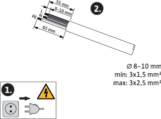
- To protect against leakage and for strain relief to the threaded cable gland, use a connection cable with sufficient outer diameter.
- The cables near the screwed connection are to be bent to form a drain loop, to drain any accumulated drips.
- Use a heat-resistant connection cable if fluid temperatures exceed 90 °C.
- Lay the connection cable in such a way that it touches neither the pipes nor the pump.
Terminals are intended for rigid and flexible conductors with or without ferrules.
Connection | Terminal cross-section in mm2 Min. | Terminal cross-section in mm2 Max. | Cable |
|---|---|---|---|
Mains plug | 3x1.5 | 3x2.5 | |
SSM | 2x0.2 | 2x1.5 (1.0**) | * |
SBM | 2x0.2 | 2x1.5 (1.0**) | * |
Digital input 1 (DI 1) | 2x0.2 | 2x1.5 (1.0**) | * |
Digital input 2 (DI 2) | 2x0.2 | 2x1.5 (1.0**) | * |
24 V output | 1x0.2 | 1x1.5 (1.0**) | * |
Analogue input 1 (AI 1) | 2x0.2 | 2x1.5 (1.0**) | * |
Analogue input 2 (AI 2) | 2x0.2 | 2x1.5 (1.0**) | * |
Wilo Net | 3x0.2 | 3x1.5 (1.0**) | Shielded |
*Cable length ≥ 2 m: Use shielded cables.
**When using ferrules, the maximum cross-section for communication interfaces is reduced to 1 mm². All combinations up to 2.5 mm² are permissible in the Wilo-Connector.
WARNING
Electric shock!
When connecting SSM/SBM lines, care should be taken to separate the SELV section, thus ensuring SELV protection is maintained!
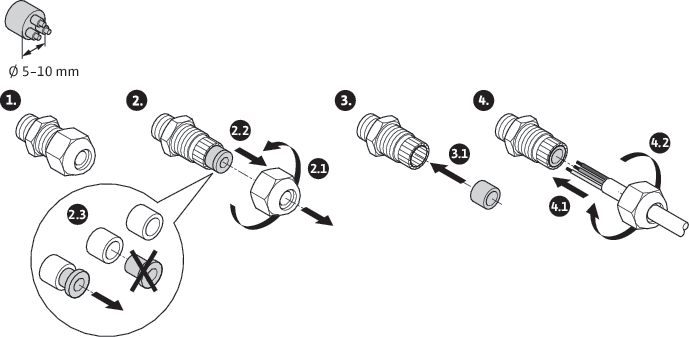
At cable cross-sections of 5 – 10 mm, remove the internal sealing ring from the threaded cable gland before installing the cable.
NOTICE
• Tighten the threaded cable gland M16x1.5 on the control module with a torque of 2.5 Nm.
• Tighten nuts with a torque of 2.5 Nm to ensure strain relief.
• Internal sealing ring of the threaded cable gland when installing cables with a diameter ≥ 5 mm.