Aligning the motor head
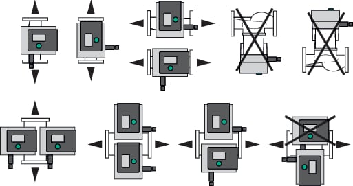
The motor head must be aligned according to installation position.
- Check permissible installation position.
NOTICE
In general, rotate the motor head before the system is filled!
Different methods may be required depending on the pump type.
Case 1: access to motor fastening screws restricted.
Single pump
- Remove heat insulation by pulling the two half shells apart.
- Carefully unplug the sensor cable from the control module.
- Loosen sensor cable from cable clips.
- Using a screw driver, carefully lift the cable clip from the motor fastening screws and keep aside.
DANGER
Risk of fatal electrical shock! Generator or turbine operation during pump flow!
Even without the module (without electrical connection), there may be dangerous contact voltage at the motor contacts!
- Loosen the screws of the module cover (HMI).
- Remove the module cover including display and carefully put it to one side.
- Loosen interior hexagonal head screw M4 in the control module.
- Remove control module from the motor.
- If required, loosen cable loop by removing the cable retention clip.
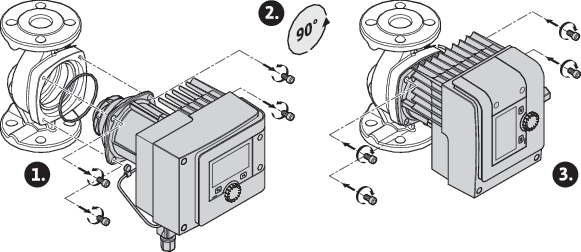
- Undo the screws on the motor housing and carefully turn the motor head. Do not remove from pump housing!
WARNING
Material damage!
Damage to the gasket or a twisted gasket can lead to leakage. Replace gasket if necessary!
- Subsequently tighten motor fastening screws diagonally. Observe the tightening torques! (Table “Tightening torques”)
- Place the control module on the motor head (guide pins specify the exact position).
- Secure the control module using M4 interior hexagonal head screws. (torque: 1.2 ± 0.2 Nm)
- Push the module cover including display forward into the grooves using the guide bars, close cover and fasten with screws.
CAUTION

Hot components!
Damage to the sensor cable caused by hot motor head!
Lay the sensor cable and guide it through the cable clip in a way that the cable does not touch the motor head.
- Insert sensor cable plug into the connector in the module.
- Press cable clip onto two motor fastening screws.
- Push the sensor cable into the provided cable guide of the cable clips.
- Place both the half shells of heat insulation around the pump housing and press together.
Case 2: access to motor fastening screws unrestricted.
- Carry out steps 1 to 4, 10 to 11 and 15 to 18 in sequence.
Steps 5 to 9 and 12 to 14 are not absolutely necessary.
Double pump
NOTICE
In general, rotate the motor head before the system is filled!
If you are forced to rotate one or both motor heads, undo the double pump cable connecting both control modules.
Carry out steps as described for the single pump:
Case 1: access to motor fastening screws restricted.
- Carry out steps 2 to 17 in sequence.
Case 2: access to motor fastening screws unrestricted.
- Carry out steps 2 to 3, 9 to 11 and 15 to 17 in sequence.
Steps 1, 4 to 8, 12 to 14 and 18 are not absolutely necessary.
Reconnect both control modules with the double pump cable. If required, loosen cable loop by removing the cable retention clip.
Tightening torques for motor fastening screws
Screw | Tightening torques [Nm] |
|---|---|
M6x18 | 8 – 10 |
M6x22 | 8 – 10 |
M10x30 | 18 – 20 |