Flange-end pump installation
WARNING

Hot surface
The pipes might be hot. There is a risk of injury due to burns.
- Wear protective gloves.
WARNING

Risk of injury and scalding due to improper installation!
The flange connection can be damaged and develop leaks if the pump is not installed correctly.
- Never interconnect two combination flanges!
- Pumps with combination flanges are not permitted for operating pressures PN 16!
- The use of securing elements (e.g. spring lock washers) can result in leakages at the flange connection. They are therefore not permitted. Use the washers supplied (scope of delivery) between screw heads/nut heads and the combination flange!
- The permissible tightening torques listed in the table below must not be exceeded, even if screws of higher strength (≥ 4.6) are used, since splintering may otherwise occur at the edges of the long holes. This may cause the screws to lose their prestress and leakage can occur in the flange connection. Risk of scalding!
- Use screws of sufficient length. The screw thread must project by at least one pitch of screw thread from the screw nut.
- Perform leakage test at maximum permissible operating pressure!
Screws and tightening torques
Flange-end pump PN 6
| DN 32 | DN 40 | DN 50 |
|---|---|---|---|
Screw diameter | M12 | M12 | M12 |
Strength class | ≥ 4.6 | ≥ 4.6 | ≥ 4.6 |
Tightening torque | 40 Nm | 40 Nm | 40 Nm |
Screw length | ≥ 55 mm | ≥ 55 mm | ≥ 60 mm |
| DN 65 | DN 80 | DN 100 |
|---|---|---|---|
Screw diameter | M12 | M16 | M16 |
Strength class | ≥ 4.6 | ≥ 4.6 | ≥ 4.6 |
Tightening torque | 40 Nm | 95 Nm | 95 Nm |
Screw length | ≥ 60 mm | ≥ 70 mm | ≥ 70 mm |
Flange-end pump PN 10 and PN 16 (no combination flange)
| DN 32 | DN 40 | DN 50 |
|---|---|---|---|
Screw diameter | M16 | M16 | M16 |
Strength class | ≥ 4.6 | ≥ 4.6 | ≥ 4.6 |
Tightening torque | 95 Nm | 95 Nm | 95 Nm |
Screw length | ≥ 60 mm | ≥ 60 mm | ≥ 65 mm |
| DN 65 | DN 80 | DN 100 |
|---|---|---|---|
Screw diameter | M16 | M16 | M16 |
Strength class | ≥ 4.6 | ≥ 4.6 | ≥ 4.6 |
Tightening torque | 95 Nm | 95 Nm | 95 Nm |
Screw length | ≥ 65 mm | ≥ 70 mm | ≥ 70 mm |
Never interconnect two combination flanges.
Installation steps

1. Close the shut-off devices in front of and behind the pump.
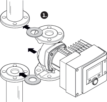
2. Insert the pump into the pipe together with two suitable flat gaskets in such a way that the flanges can be screwed to the pump inlet and outlet. Observe direction of flow! The arrow-shaped flow indicator on the pump housing must point in the direction of flow.
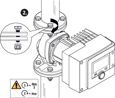
3. Screw the flange together in a crosswise manner, in 2 steps using suitable screws and the supplied washers. Observe specified tightening torques!
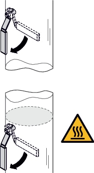
4. Open the shut-off devices in front of and behind the pump.
5. Check impermeability.